ANALYSIS AND PREDICTION OF HEAT INDUCED DEFORMATION PRODUCED BY THE LINE HEATING PROCESS USING THE FINITE ELEMENT METHOD
Adán Vega Sáenz Ph. D.
Universidad Tecnológica de Panamá
[email protected]
ABSTRACT
To get an insight into the relationship between heating conditions and inherent deformation, the key to automate the plate forming by line heating, a series of experiments and/or numerical analyses is required. To replace costly experimental work, the finite element method (FEM), which is considered the most effective tool, is used in analysis. Two different analyses are required, namely heat conduction and thermal-elastic-plastic deformation analyses. In both of them a mesh model is need. In order to choose the most appropriate mesh model, the relationship between degree of freedom (DOF) and the computational time plays a key role. It is a fact that the usage of small element in the heating area increases the accuracy of the predictive model increasing the DOF. As is well known, a large number of DOF may result in an unrealistic computing time even if faster computer are used. Therefore, it is necessary to find the most appropriate mesh model that can be used to simulate different plate size under acceptable time.
In this paper, a study on the best practices for analysis and prediction of the inherent deformation produced by line heating is first given. Then to a procedure that can be used to select the most appropriate mesh model for analysis of the line heating process is presented. The discussion includes: the influence of the model size, the number of elements through the thickness and the size of the elements. The analysis also considers the case of multiple heating lines. Finally, recommendations about selection of mesh model are presented.
Key worlds: Line heating, Plate Forming, Meshing, Numerical Simulation, Finite Elements Methods.
RESUMEN
Para comprender la relación entre las condiciones de calentamiento y las definiciones inherentes, que es la clave para automatizar el formado de placas mediante calentamiento en línea, se requiere una serie de análisis numéricos y/o experimentos. Para remplazar costosos trabajos experimentales, el método de Elementos Finitos, el cual es considerado la herramienta más efectiva, es usado en análisis. Dos tipos de análisis diferentes son necesarios, conducción de calor y análisis de deformaciones termo-elásticas- plásticas. En ambos casos se necsita un modelo de malla. En la selección del modelo de malla más apropiado la relación entre el grado de libertad y el tiempo de computación juega un papel clave.
Es un hecho que el uso de elementos pequeños en la zona de calentamiento incrementa la exactitud del modelo predictivo, incrementando el número de grados de libertad. También como es sabido, el uso de un gran número de grados de libertad puede resultar en tiempos de ejecución no realistas aún con computadoras más rápidas. Por lo tanto hay que encontrar el modelo de malla más apropiado para simular diferentes tamaños de placas con tiempos de ejecución aceptables.
En este artículo, se presenta primero un estudio sobre las mejores prácticas para el análisis y predicción de las deformaciones inherentes producidas por el calentamiento en línea. Luego, un procedimento para seleccionar un modelo de malla más apropiado para el análisis del proceso de calentamiento en línea es presentado. La discusión incluye: la influencia del tamaño del modelo, el número y el tamaño de los elementos a través del espesor. El análisis también considera el caso de múltiples líneas de calentamiento. Finalmente, la redomendaciones sobre la selección del tamaño del modelo son pesentadas.
Palabras claves: Calentamiento en línea, formado de placas, mallado, simulación numérica, Método de Elementos Finitos.
1. INTRODUCTION
Forming by line heating has been an active research topic in manufacturing, especially in shipbuilding. The problem of forming by line heating can be divided into two sub-problems: the heat transmission problem and the elasto- plastic deformation problem. The first problem has been widely studied and efficient techniques have been presented (Moshaiov and Latorre (1985), Tsuji and Okumura (1989), Terasaki, Kitamura and Nakai (1999), Chang, Liu, and Chang (2005), Ling and Atluri (2006), Liu (2006), Liu, Liu, and Hong (2007), Osawa, Hashimoto, Sawamura, Kikuchi, Deguchi, and Yamaura (2007)). The elasto-plastic deformation problem has been also widely studied. Theoretical researches on the mechanism of line heating process aimed to predict the final shape of a metal plate when given the heating conditions and mechanical properties of the plate material exists (e.g. Moshaiov and Vorus (1987), Moshaiov and Shin (1991), Jang, Seo and Ko (1997), Kyrsanidi, Kermanidis and Pantelakis (1999)). However, most of these investigations have focused on the deformation produced by single heating lines on small plates, no empirical method or inherent strain database has been developed for actual size plates and considering multiples heating lines.
The author has developed a practical and accurate method to predict deformation of actual size plates such as those used in shipbuilding, aerospace, cars, etc,. As a fundamental component of this method, a line heating inherent deformation database was created. This inherent deformation database besides being mainly dependent on primary factors such as the plate thickness, the heat source speed and the heat input, it also takes into account secondary factors such as the geometry of the plate, the cooling condition, the location of the heating line, multi- heating lines, heat-induced curvature, residual stresses and inter-heating temperature. Here, it is to be noted that the influences of these secondary factors are not so simple that they can be linearly related to primary factors. Also, it was difficult to obtain these influences by experiments because of the large scatter in test results. Therefore, to clarify the influence of these secondary factors on inherent deformation 3D thermal-elastic- plastic FEM was utilized.
In this report, a numerical study is performed to evaluate the influence of the finite elements mesh model on the accuracy of the results obtained through numerical analysis. First, a finite element analysis (FEA) is established. Then, through experiments of line heating and comparison with commercial software, the accuracy of this FEA is evaluated. After that, using the FEA previously developed, a series of computation are carried out to evaluate the influence of meshing on inherent deformation. Finally, through the analysis of the results, conclusions of the influence of meshing on inherent deformation of plates undergoing line heating are presented and recommendations about mesh selection are given.
2. LINE HEATING PROCESS
When a plate is being thermo-mechanically formed, plastic deformations are produced by the thermal stresses generated during heating and subsequent cooling of the plate. During this process, one side of the plate is heated while the other side is kept cooler. The temperature gradient in the material across the thickness causes thermal strains that, in turn, cause the plate to bend downwards (convex heated surface). In the meantime, the expanding metal is constrained by the surrounding cooler metal, and compressive stresses result. As the yield stress decreases with heating, the heated metal yields and plastic compressive strains are produced. When the heat is removed, the plate cools down and the metal recovers its strength and contracts. The plate will then deform and assume an equilibrium state in the direction opposite to that when it was heated. That is bending upwards (concave heated surface). The curvature generated is mainly governed by the surface temperature and the temperature gradient between the top and bottom surfaces of the plate.
An ideal thermo-mechanical forming system would be able to heat a whole steel plate instantly with desired temperature gradients at all point of the plate. This system cannot be realized because of two reasons. First, it involves a very large heating pad that should be able to heat the whole plate at one time. Second, the heat flux distribution should be adjusted according to the desired temperature gradients at all points of the plate. This system is presently prohibited by economic and processing constraints. Instead, line heating forming processes using gas torch, induction heating or more recently laser heating have been widely used in various industries, such as shipbuilding, aerospace, and automotives. In these processes, basically, the principle is to apply a combination of heating lines in different direction until attaining the desired shape.
3. NUMERICAL ANALYSIS OF THE LINE HEATING PROCESS
In this section a brief resume of the main components of the numerical analysis is presented.
3.1 Finite Element Software used in numerical simulation
The process of plate forming by line heating is a coupled nonlinear thermo-mechanical process, which makes numerical modeling difficult. However, numerical simulation is a very effective alternative to experiments, and in case of line heating, computed results obtained through well-designed serial computations yield information that is otherwise unavailable. Although numerical simulation of line heating process such as FEM analysis has achieved considerable success in predicting plate deformation, the computational time is typically very long which makes FEM analysis not suitable for real-time analysis.
The thermo elastic-plastic analysis used in simulating the line heating process is similar to that of the welding process. The basic procedure followed in the analysis is outlined in the schematic diagram shown in Figure 1. The differences between welding and line heating are mostly due to the higher temperatures produced during welding. In addition, the welding processes includes other factors such as melting and solidification of the material, phenomena inexistent during plate forming by line heating. However, with the appropriate usage, the same FEM programs can be used for both analyses. In this paper a program based on the ISM method, which was developed in our laboratory [See Nishikawa et al,.], is used to simulate plate.
3.2 Thermal analysis
In thermal analysis by the FEM, an idealized heat source model is introduced. In this idealized heat source model the heat input is given to a hexagonal volume of dimensions 40 mm (length) x 80 mm (width) x h/4 (depth). In all the studied cases, the highest temperature on the heated surface in the heating zone is kept at about 800°C. Thermal boundary conditions are such that heat transfer by convection and radiation is permitted at the plate surfaces. Temperature dependent thermal properties of mild steel as shown in Fig. 2 are used in this research. Figure 3 shows a typical distribution of temperature along the heating line (a) and through the plate thickness (b) obtained for the simulation of a single heating line. A straight heating line applied from edge to edge along the center of the plate is nalyzed. This heat source is assumed to move with a constant speed of 3 mm/sec. The net heat input is equal to 5 kJ/mm. As may be seen in Fig. 3 (b), only the region close to the heating surface is under high temperature (equal or close to 800 °C).
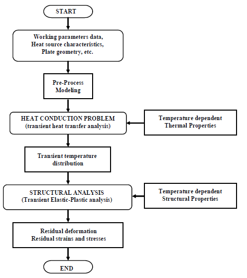
Figure 1. Schematic of the 3D thermo elastic- plastic analysis using FEM
3.3 Mechanical Analysis
The transient temperature distribution obtained from the heat transfer analysis is employed as a thermal load in the subsequent mechanical analysis. Stresses, strains and displacements are then computed. Temperature dependent material properties of mild steel shown in Figure 4 are used in this research. Figure 5 shows a plate model with the mechanical boundary condition.
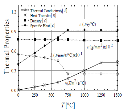
Figure 2. Temperature dependent thermal properties of Mild steel
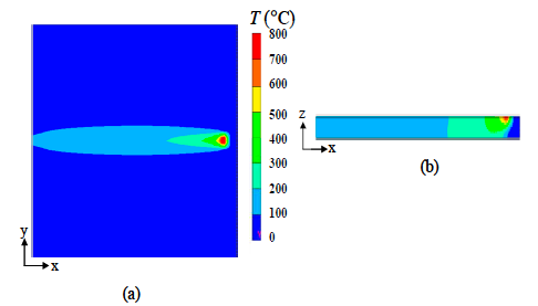
Figure 3. Typical temperature distributions (a) Along the heating, (b) Through the thickness
The same finite element model used in the thermal analysis is employed in mechanical analysis. Figure 6 shows the distribution of residual stresses along the heating line and through the plate thickness as typical example of the mechanical analysis.
3.4 Representation of the results
In the case where a plate has a large length/thickness ratio, such as a ship hull plate, only two of the six components of inherent strain; ε x* (in the line heating direction) and εy* (in the transverse direction) are dominant. Based on this assumption, plate deformation produced by line heating can be described by four deformation components as is shows in Figure 6.
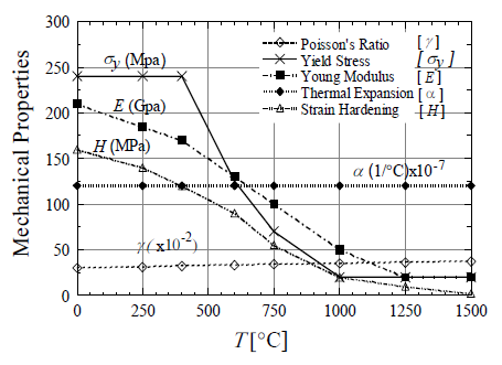
Figure 4. Temperature dependent mechanical properties of Mild steel
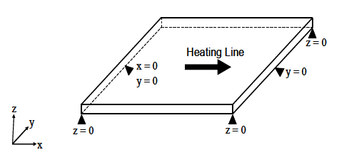
Figure 5. Typical mechanical boundary conditions
These deformation components (inherent deformation) named as: inherent longitudinal shrinkage (δix), inherent transverse shrinkage (δiy), inherent longitudinal bending (θix) and inherent transverse bending (θiy) are defined as the integration of inherent strain over the cross section normal to the heating line as follows;
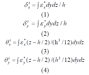
Where, x and y are the coordinates in the directions of the heating line and transverse to the heating line, respectively, and h is the thickness of the plate.
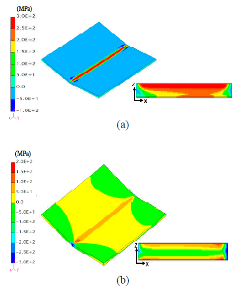
Figure 5. Typical distributions of residual stresses (a) σx and (b) σy
3.5 Validation of the numerical results through Comparison with experiments of line heating and with commercial codes
In order to validate our numerical results two different studies were performed, first, comparison with line heating experiments were carried out, then comparison with commercial codes were performed. In this section a brief introduction to these comparisons is presented.
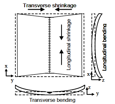
Figure 6. Types of line heating deformation
3.5.1 Comparison with line heating experiments
Experiments of multiple heating lines using the automatic induction heating system IHI-α (Tango et al,.) were performed aiming to corroborate the numerical results. Figure 7 shows the plate model used in the experiment. Where, three heating lines, named as heating A, B and C are applied. The heating sequence is as follows: B → C → A. During the experiment, before applying heat, the plate was cooled down to room temperature. In this way, the influences of parallel and crossed heating lines were evaluated for the same experiment avoiding influences of inter-heating temperature. The heating and cooling conditions, as well the geometry of the heating source, are the same for all the heating lines.
At the beginning, small holes were drilled at the point of measurements on the top and bottom surface. To evaluate the plate deformation, distances between these measuring points located
along the heating line are measured before and after each heating. Shrinkage and bending produced by each heating line is subsequently evaluated. Figure 8 shows a comparison of the distribution of the longitudinal shrinkage obtained from experiments and that obtained by simulation of a straight heating line (Alone heating B, before applying heating C and A). Where, simulation results agree quite well with experimental results. Both, the longitudinal shrinkage and its variation along the heating line are well captured by the numerical model.
Comparison with Commercial Codes
In order to validate our FEM results, the transient temperature field for TIG melt process was computed and the results were compared with those computed using different commercial FEM codes. Numerical analyses were conducted separately at the University Of Bristol (UOB), Rolls Royce plc (RR), Insa-Lyon / Areva energy (INSA/AREVA) and our research group (Joining and Welding Research Institute). The detail of the modeling was left to the discretion of the individual analysts. In all the cases, due to the symmetry of the plates and welds, half-plate models were used.
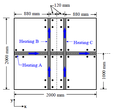
Figure 7. Plate model used to estimated deformations produced by experiments of line heating
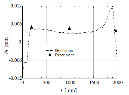
Figure 8. Comparison between results obtained from experiments and by simulation of multiples heating (Plotted along heating B)
Temperature dependent material properties of a 316L stainless steel were used by all the analysts. The analysis performed by the University of Bristol was using ABAQUS 6.61 while Rolls-Royce plc used CTSP-solid, which is part of the Virtual Fabrication Tool (VTF) software package and Insa-Lyon / Areva Energy used the Code-Aster finite element code.
The characteristics of the plate model, the welding conditions and the position of the measurement points are given in Table 1. The recorded thermocouple temperature is compared with those predicted by the thermal FE analysis. Figure 9 shows the comparison. A good agreement is observed among the temperatures predicted by using the FEM employed in this research, others thermal models and experimental measurements. Similar tendency is observed in Figure 10 where the distribution of residual stress along the welding line is compared (See Lewis et al. for more details).
Table 1. Plate model and welding conditions used to validate the FEA
| Arc Time |
Current |
Voltage |
Travel rate |
Heat Input (η= 100%) |
| 100 sec |
156 A |
12.4 V |
108 mm/min |
1.075 KJ/mm |
|
| Plate geometry |
Material |
Location of the termocouples |
Length=180mm Width=130mm Thickness=20mm |
AISI Type 316L sustenitic steel |
T1 X=90; Y=53mm; Z=20mm |
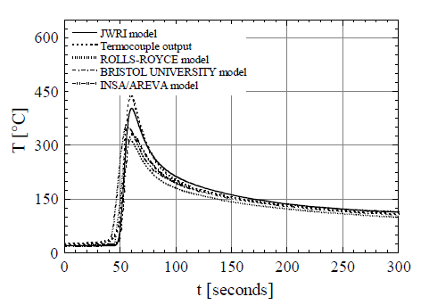
Figure 9. Temperature histories (heated surface)
4. Results and discussions
During forming by line heating, the heat source moves and only the area that is very near to the heat source undergoes high temperature and plastic deformation. The remaining area of the plate has small changes of temperature and small amount of stresses and no plastic strains. This implies that the FEA can be done by using dense mesh only in these areas, while in the remaining area, sparse meshes can be used. In this way, the computational time is greatly reduced. However, when the plate to be analyzed is large, computational time greatly increases limiting the computation using available commercial codes even in a modern strong computer environment. In addition, in analyzing the line heating process, many influential factors need to be taken into account. In real forming practice, plate size and the final shape vary from case to case. The variation of geometrical shapes of plate to be formed can be infinite. Therefore, to deal with forming of specific shapes is ineffective from the engineering point of view. In addition, it is well known that usage of small plates does not yield accurate predictions of plate deformation due to line heating (Vega et al, 2008). On the other hand, usage of large models requires large computational time. Aiming to find the most appropriate FEM model to be used, we studied the influence of meshing on computed plate deformation. A resume of the result of these studies is presented in this section.
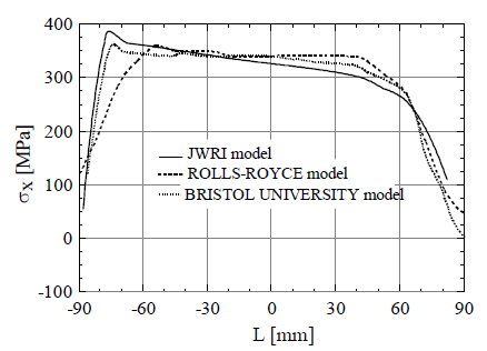
Figure 10. Residual stress distribution (Top surface)
4.1 Influence of the model size on inherent deformation
Various investigations of the effect of plate size (size effect) on heat-induced deformation have been presented. Most of them have focused on the effect of plate thickness and no research can be found that has considered plates larger than one (1) meter. In this section, the influence of plate size, including variation of plate length and plate width on inherent deformation is investigated.
Figure 11 shows the variation of longitudinal shrinkage with plate length while plate width and thickness are kept constant. Heat input and speed of the heat source are also kept constant in all cases. It may be seen that, maximum inherent longitudinal shrinkage in small plates changes with plate length. However, for plates larger than approximately 800 mm, maximum inherent longitudinal shrinkage is almost the same.
As may be observed in Figure 11, the distribution of longitudinal shrinkage for large plates is mostly uniform at the central region of the plate while toward the edges of the plate is not. This suggests that if small plates model are used (600 mm for example) the results will be underestimated. It is also observed that the region at the plate edges with complex distribution of residual stress extends more or less 400 mm toward the plate center. Thus, it is necessary to use plate models larger than 800 mm to avoid the underestimation of inherent deformation.
Figure 12 shows the variation of transverse shrinkage with plate width while plate length and thickness are kept constant. It may be observed that in the case of narrow plates (400 mm), there is a small reduction of the maximum inherent transverse shrinkage compared with that obtained in wide plates. From this figure, it may be seen that only in narrow plates, an appreciable variation of inherent deformation is observed. Similar behavior is seen after analyzing the variation of other components of inherent deformation.
Despite the fact that inherent deformation is influenced by plate size, as is demonstrated, this influence is only observed in small plates. For large plates, the inherent deformation at the central region of the plate does not significantly depend on plate size. It is also important to note that the distribution of inherent deformation at the beginning of the heating line (entrance edge) does not vary with plate size. Similar tendency is observed at the end of the heating line (exit edge). The variation of inherent deformation at both plate edges is well known as edge effect and it has been clarified by the author (See Vega, 2009).
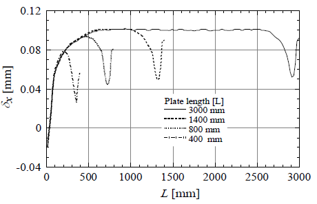
Figure 11. Variation of longitudinal shrinkage with plate length
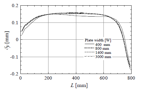
Figure 12. Variation of transverse shrinkage with plate width
From the results of these two analysis it is clearly observed that the size of the plate model play a key role in predicting inherent deformation. Thus, contrary to most of the existing studies, in simulating the line heating process, such small model may not be used. Instead, model larger than 800 mm are recommended.
4.2 Influence of element size on prediction of inherent deformation
To obtain accurate prediction of the deformation, the distribution of temperature at the heating area obtained by FEM need to be similar to that of the heating source. In order to attain the most accurate temperature distribution, the element size in the heating area needs to be as small as possible. However,
small elements increase the DOF and therefore the computational time.
Aiming to investigate the influence of element size on prediction of inherent deformation, we evaluate four (4) different mesh densities as shown in Table 2. In all the cases the plate size, the heating and the cooling condition are the same. The heat input is introduced in an area of 80 mm width, 40 mm of length and 10 mm thick from the plate surface. The characteristics of each mesh model are shown in the table.
Figure 13 shows the comparison of longitudinal and transverse shrinkage obtained by each case. As it may be observed, the usage of element sizes equal to 20 x 20 x 10 mm underestimates the inherent deformation in about 15% compared with that of an element size equal to 5 x 5 x 2.5 mm.
Table 2 Models used to study the influence of element size on prediction of inherent deformation
| Model No. |
Elements Size (mm) |
Degree of Freedom |
Computational Time (Seconds) |
| Thermal Analyses |
Mechanical Analyses |
| Model 1 |
20x20x10 |
2.7x10⁴ |
420.3 |
456 |
| Model 2 |
10x10x10 |
6.5x10⁴ |
958 |
739.7 |
| Model 3 |
5x5x5 |
5x10⁵ |
13159.1 |
8588.4 |
| Model 4 |
5x5x2.5 |
6.1x10⁵ |
42722.7 |
11283.6 |
Although the inherent deformation is underestimated when large elements are used, the computational time in case of using element of size 5x5x2.5 mm is about sixty (60) times larger than that of 20x20x10 mm. Based on the results we can concluded that even when we lost certain degree of accuracy using large element sizes, this lost is insignificant when we compare the time we save in computing each model. Very much important when we think about thousands of analysis, the number needed in order to create an automatic line heating system.
4.3 Influence of number of elements through the plate thickness
To acquire a better comprehension of the influence of the number of element through the plate thickness on inherent deformation we compare the inherent deformation caused by three cases shown in Fig. 14. In Model 1, the heat input is introduced in the first element from the heating surface. In Model 2, which has the same element size of Model 1, the same amount of heat input is introduced in the first two elements. Finally, in Model 3, the same heat input is introduced in the first element with the difference that in this model there are only four elements in the thickness direction.
Figure 15 compares the transverse shrinkage obtained after simulating a partial line heating. As it may be observed, the results of Model 1 and Model 2 are mostly similar while the Model 3 is slightly smaller. However, this difference is small and can be neglected. In addition since the computational time in Model 3 is about 10 times less than in Model 1 and Model 2, it allows us to build a more complete inherent deformation database in a short time sacrificing certain percentage of accuracy. Here is important to mention that in case of 3D thermo elastic-plastic analysis by FEM, the usage of less than four elements through the plate thickness is not a good practice since the bending components of inherent deformation will not be accurately predicted.
4.4 Effective mesh models for computing the line heating process
In order to select the FE mesh model two situations need to be considered; first is when predicting inherent deformation produced by a single heating line and second is when predicting that produced by multiple heating lines. In the first case, FE analysis can be performed using a mesh model with sparse node distribution far from the heating area. However, in the case of analyzing multiple heating lines, the possible options of meshing are limited. An example of a mesh model for multiple heating lines is shown in Figure16.
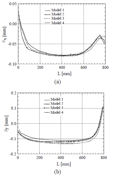
Figure 13. Influence of element size on (a) Longitudinal shrinkage, (b) Transverse shrinkage
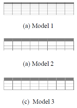
Figure 14. Models used to study the influence of number of elements through the plate thickness on inherent deformation
As it may be seen from the figure, if an additional heating line is applied, a new mesh is needed. So, the number of degree of freedom will be increased and therefore the computational time. Although small elements in the heating area are necessary to attain high accuracy in prediction of inherent deformation (as it is demonstrated before), it also increases the number of degrees of freedom and consequently the computational time. In addition, it is necessary to study the influence of multiples heating lines such as parallel and crossed on inherent deformation. Thus, flexible mesh models which can be used for multiples heating lines are needed.
Table 3. Characteristics of the models used to study the influence of number of elements through the thickness on prediction of inherent deformation
| Model No. |
Elements Size (mm) |
Degree of Freedom |
Computational Time (Seconds) |
| Thermal Analyses |
Mechanical Analyses |
| Model 1 |
20x20x10 |
2.7x10⁴ |
420.3 |
456 |
| Model 2 |
10x10x10 |
6.5x10⁴ |
958 |
739.7 |
| Model 3 |
5x5x5 |
5x10⁵ |
13159.1 |
8588.4 |
To overcome this situation, and base in numerical and experimental results, we propose the usage of meshes model with uniform distribution of elements trough the plate length, width and thickness, as shown in Figure 17. This type of mesh model can be use without limitation to study any kind of 3D thermal elastic-plastic process including line heating. The only restriction will be the size of the source. In case of line heating, it usually varies from 60 to 100 mm, thus the usage of element size such as 20mm x 20mm x (a quarter of the thickness) is good enough to acquire high enough precision of inherent deformation predicted by FEM.
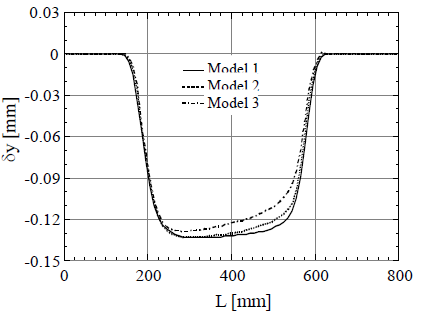
Figure 15. Influence of number of element through the plate thickness on transverse shrinkage
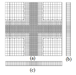
Figure 16. Example of mesh model needed in case of simulating crosses heating lines (a) Top surface, (b) along the heating line and (c) Transverse to the heating line
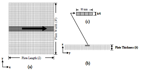
Figure 17. Typical mesh model used in simulating the line heating process, (a) Top surface, (b) Mesh distribution through the plate thickness, (c) Area of heating.
CONCLUSIONS
From the analysis of the results of this numerical study we can draw the following conclusions:
1- Based on the results of comparing our code with other codes and with experiments, we can conclude that the FEA established in this paper is appropriate to study the 3D thermal- elastic-plastic mechanism of the line heating process.
2- It has been demonstrated that in simulating the line heating process, the usage of plate model smaller than 800 mm underestimate the inherent deformation.
3- After examining different combination of element sizes and number of element through the plate thickness we can conclude that the usage of an element of size equal to 20 mm large x 20 mm width x one quarter of the plate thickness is appropriate for predicting the inherent deformation in reasonable time without losing appreciable accuracy.
4- In simulating multiples heating lines it is necessary to use mesh model with uniform distribution of elements in the heating direction, in the transverse direction and through the plate thickness.
ACKNOWLEDGMENTS
Financial support from New Energy and Industrial Technology Development Organization (NEDO) through the Japan Space Utilization Promotion Center (JSUP) in the program of Ministry of Economy, Trade and Industry is gratefully acknowledged.
REFERENCES
1. Chang, C.W.; Liu, C.S. and Chang, J.R. (2005): A Group Preserving Scheme for Inverse Heat Conduction Problems. CMES: Computer Modeling in Engineering& Sciences, 10, 1, pp.13-38.
2. Jang, C. D.; Seo, S.; Ko. D. E. (1997): A study on the prediction of deformations of plates due to line heating using a simplified thermal elasto-plastic analysis. Journal of Ship Production, 13(1):22-27.
3. Kyrsanidi, A. K.; Kermanidis, T. B.; Pantelakis S. G. (1999): Numerical and experimental investigation of the laser forming process. Journal of Materials Processing Technology, 87:281-290.
4. Lewis, S. J., Alizadeh, H., Gill, C., Vega, A., Murakawa, H., El-Ahmar, W., Gilles, P., Smith, D. J., Truman, C. E.: Modeling and measurement of residual stresses in autogenously welded stainless steel plates: Part 1 – Fabrication and modeling, 2009
5. Ling, X. and Atluri, S.N. (2006): Stability Analysis for Inverse Heat Conduction Problems. CMES: Computer Modeling in Engineering & Sciences, 13, 3, pp.219-228.
6. Liu, C.S. (2006): An Efficient Simultaneous Estimation of Temperature-Dependent Thermophysical Properties. CMES: Computer Modeling in Engineering & Sciences, 14, 2, pp.77-90.
7. Liu, C.S.; Liu L.W. and Hong, H.K. (2007): Highly Accurate Computation of Spatial-Dependent Heat Conductivity and Heat Capacity in Inverse Thermal Problem. CMES: Computer Modeling in Engineering & Sciences, 17, 1, pp.1-18.
8. Moshaiov, A. and Latorre, R. (1985): Temperature Distribution during Plate Bending by Torch Flame Heating. Journal of Ship Research, 29, 1, pp.1-11.
9. Moshaiov A.; Shin, J. G. (1991): Modified strip model for analyzing the line heating method-part 2: Thermo-elastic-plastic plates. Journal of Ship Research, 35(3):266-275.
10. Moshaiov A.; Vorus, W. S. (1987): The Mechanics of the Flame Bending Process: Theory and Applications. Journal of Ship Research, 31(4):269-281.
11. Nishikawa, H.; Serizawa, H.; Murakawa, H. (2005): Development of a Large-scale FEM for Analysis Mechanical Problems in Welding, Journal of the Japan Society of Naval Architects, 2, pp.379.
12. Osawa, N.; Hashimoto, K.; Sawamura, J.; Kikuchi, J.; Deguchi, Y. and Yamaura, T. (2007): Development of Heat Input Estimation Technique for Simulation of Shell Forming by Line-Heating. CMES: Computer Modeling in Engineering & Sciences, 20, 1, pp.45-53.
13. Tango, Y, Ishiyama, M, Nagahara, S, Nagashima, T, and Kobayashi, J, (2003). "Automated Line Heating for Plate Forming by IHI-ALPHA System and its Application to Construction of Actual Vessels-System Outline and Application Record to date," Journal of the Society of Naval Architects of Japan. Vol. 193. pp. 85-95.
14. Terasaki, T.; Kitamura, N. and Nakai, M. (1999): Predictive Equation for Thermal Cycle Generated by Line Heating Method. Trans. The West-Japan Soc. Naval Architects, 99, pp.321-329 (in Japanese).
15. Tsuji, I. and Okumura Y. (1988): A Study on Line Heating Process for Plate Bending of Ship Steels. Trans. The West-Japan Soc. Naval Architects, 76, pp.149-160 (in Japanese).
16. Vega, A., Rashed, S., Tango, Y., Ishiyama, M., Murakawa, H.: Analysis and prediction of multi-heating lines effect on plate forming by line heating. CMES Journal: Computer Modeling in Engineering & Sciences, CMES, Vol. 28, No. 1, pp. 1-14, 2008
17. Vega, A.: Development of Inherent Deformation Database for Automatic Forming of Thick Steel Plates by Line Heating Considering Complex Heating Patterns. Doctoral Thesis. Osaka University, Japan, 2009.